-
Company
-
Product
-
NdFeB Magnets
-
SmCo Magnets
-
AlNiCo Magnets
-
Ferrite Magnets
-
Bonded Magnets
-
FeCrCo Magnets
-
Rubber Magnets
-
Other Magnetic Materials
-
Nanocrystalline Core
-
Common Mode Inductors
-
Amorphous Inductors
-
Amorphous Reactors
-
AlNiCo Holding Magnets
-
NdFeB Holding Magnets
-
Magntic Lifters
-
Magnetic Tubes & Grates
-
Halbach Arrays
-
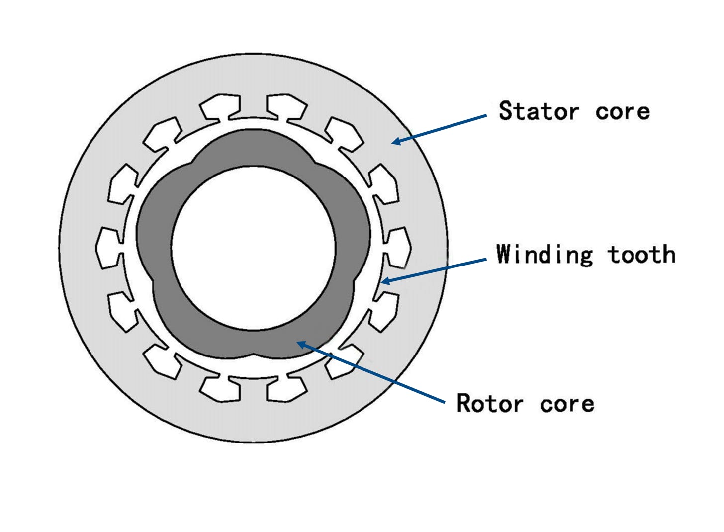
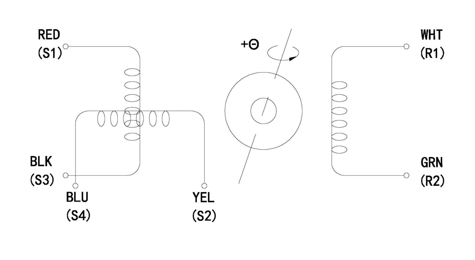
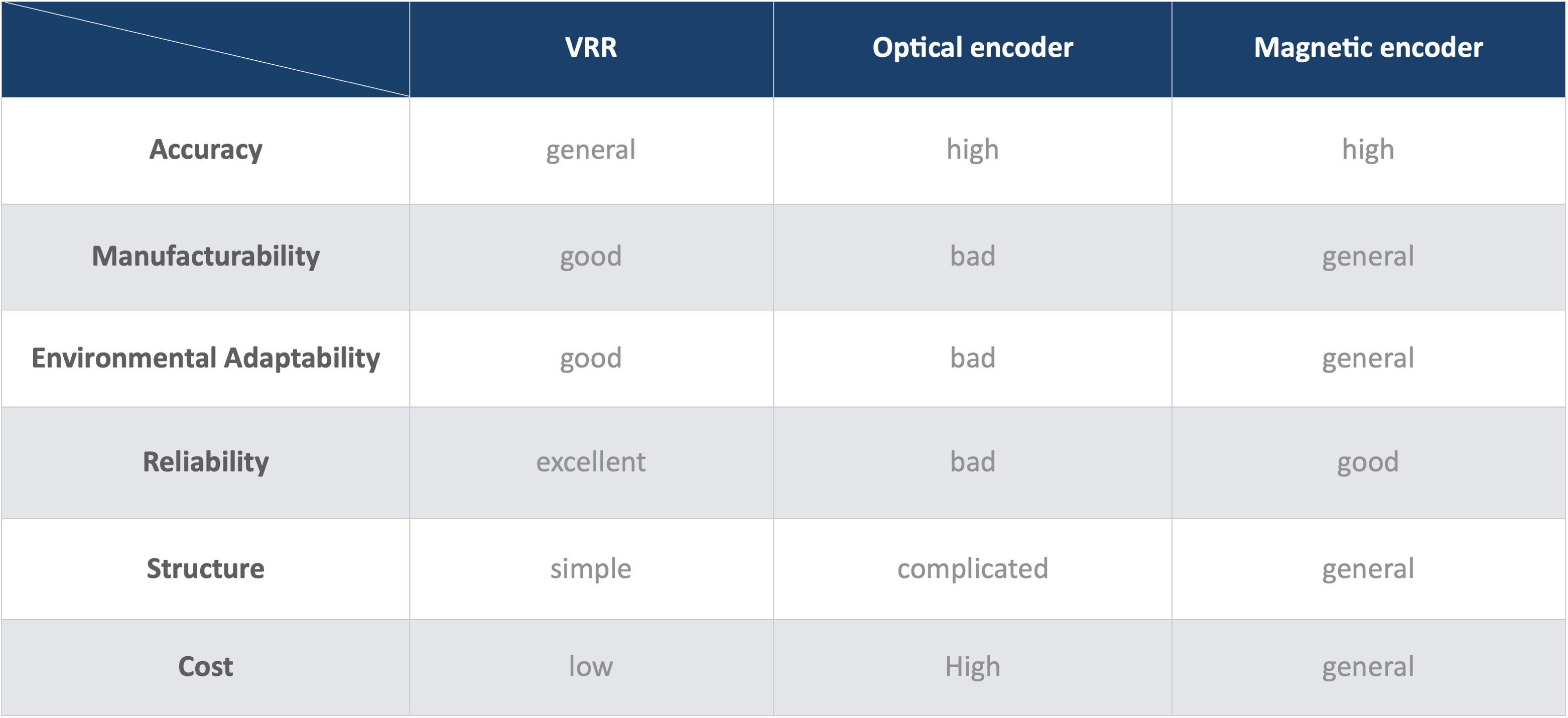
Resolver
-
Overmolding Magnets
-
Customized Magnet Assemblies
-
Powder Injection Parts
-
-
Capabilities
-
Resources
-
Contact
-
Subscription
-
-
Company
-
Product
-
Products Overview
-
NdFeB Magnets
-
SmCo Magnets
-
AlNiCo Magnets
-
Ferrite Magnets
-
Bonded Magnets
-
FeCrCo Magnets
-
Rubber Magnets
-
Other Magnetic Materials
-
Nanocrystalline Core
-
Common Mode Inductors
-
Amorphous Inductors
-
Amorphous Reactors
-
AlNiCo Holding Magnets
-
NdFeB Holding Magnets
-
Magnetic Lifters
-
Magnetic Tubes & Grates
-
Halbach Arrays
-
Rosolver
-
Overmolding Magnets
-
Customized Magnetic Assemblies
-
PIM Parts
-
-
Capabilities
-
Resources
-
Contact
-
Subscription
-